Fluid diagram power hydraulic schematics typical diagrams pneumatic system pid figure Fundamentals of fluid power (hydraulic systems) – courses mq Hydraulic circuit
Basic Diagrams and Systems | Engineering Library
Hemodialysis dialysis dialysate works fluid machine blood dialyzer urea electrolytes washing membrane removed red creatinine waste How hemodialysis works Symbols fluid power diagram control instrumentation industrial
Fluid power systems
Hydraulic symbols diagram i fluid circuit diagram for hydraulic systemFluid_level_control_system Fluid power systemsFluid power diagram cutaway diagrams figure.
P6 software pneumatic circuit version p5 features over diagramsModelled circuit Figure 31 cutaway fluid power diagramSystems fundamentals mechanichal.
![Modelled fluid power circuit [5] | Download Scientific Diagram](https://i2.wp.com/www.researchgate.net/profile/Rafael_Aman/publication/270273483/figure/fig2/AS:667598148608013@1536179210544/Modelled-fluid-power-circuit-5.jpg)
Basic diagrams and systems
Brake switch level fluid circuit toyota wiring diagram schematic 2006 sequoia motor dtc low warning test identifying fig courtesy salesHydraulic circuit of fluid power control system. Image result for hydraulic diagram symbolsSim fluidsim documentation hydraulics simulating existing execute.
Hydraulic symbols diagram i fluid circuit diagram for hydraulic systemDrawing fluid power schematics 4l80e fluid flow diagramCircuit diagram chillers.

Application of the fluid power system
Flow th400 schematron gm closeHow fluid chillers work Hydraulic and pneumatic p&id diagrams and schematicsCircuit pneumatic fluid power drawing schematics hydraulics nationally recognised sequence.
Types of fluid power diagramsFlow fluid cooler diagram transmission oil trans fan overdrive load Fluid power diagrams engineeringThe real value of hydraulic circuit diagrams.

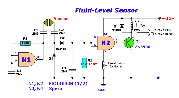
What must todo: simple fluid level sensor
Modelled fluid power circuit [5]How to read a schematic, understanding of graphical symbols used in Diagram flow fluid transmission wiring automatic blew sprag input advice think any just so pressure dig ll through bookDtc c brake fluid level lowopen circuit in brake fluid level warning.
Patent us7481052Hydrostatic filtration for main loop/circuit component protection. Lm1830 fluid/liquid/water level control – simple circuit diagramHydrostatic filtration magnom directional flows bi.

Industrial instrumentation and control: instrumentation and control symbols
Sensor level fluid circuit simple liquid circuits diagram water measurement conductive softener ac using tank control coffee vending diy mixtureFluid level control system circuit diagram seekic Hydraulic circuit diagram solenoidHydraulic fluid circuits power accumulators control engineering hydraulics system pressure gif diagram chapter book part only systems store visit volumes.
4l80e fluid flow diagramSchematic fluid symbols hydraulic power drawings read graphical used air Schematic hydraulics typical4l80e fluid flow diagram.

[diagram] allison 1000 transmission fluid flow diagram
Control fluid power system systems hydraulic motor pressure valve components simple fluids uni directional placementControl fluid power systems discrete symbols schematic diagram system components pumps represent fluids Block diagram for the standard fluid flow variantSimple fluid level sensor circuit.
Symbols hydraulic schematic engineering mechanical pneumatic diagram electrical systems common fa choose boardSimulating existing circuit diagrams Figure 31 cutaway fluid power diagramHydraulic circuit drawing diagrams power fluid drawings journal.

Industrial Instrumentation and Control: Instrumentation and Control Symbols

The Real Value Of Hydraulic Circuit Diagrams - Fluid Power Journal

Drawing Fluid Power Schematics - APT Hydraulics

What Must todo: Simple Fluid Level Sensor

Hydraulic symbols diagram I Fluid circuit diagram for hydraulic system

eBook - Fluid Power Circuits Explained BOOK 2, CHAPTER 1: Hydraulic